Acceptance Check for Detailed PV Geometry and Thermal Inputs

Cinn Song
Founder & Chief Solutions Architect
TL;DR
Pass only when module geometry, thermal setup, system sizing, GCR, and shading/layout assumptions are consistent across the SAM case; otherwise hold for correction or evidence.
The acceptance check should verify that Module page geometry and thermal inputs match the same physical array described on the System Design and Shading/Layout pages. If rows, columns, mounting, GCR, clearance, or bifacial inputs conflict, the model should be held until corrected.
Summary
The acceptance check should verify that Module page geometry and thermal inputs match the same physical array described on the System Design and Shading/Layout pages. If rows, columns, mounting, GCR, clearance, or bifacial inputs conflict, the model should be held until corrected.
Key Takeaways
- Verify Module page rows and columns against System Design and Shading/Layout because SAM states these values are independent and should be checked for consistency.
- Confirm module area, module width, and calculated module length describe the same module geometry used for system sizing.
- Check that detailed PV total module area is consistent with single-module area multiplied by the number of modules in the system.
- Confirm mounting configuration because SAM uses it to model airflow and heat transfer and assumes all modules use the same mounting configuration.
- For bifacial arrays, reconcile ground clearance, transmission fraction, bifaciality, GCR, albedo, and row spacing before accepting results.
- Mark missing or conflicting layout evidence as unknown; do not infer performance, savings, or product specifications from general modeling guidance.
Acceptance Check for Detailed PV Geometry and Thermal Inputs
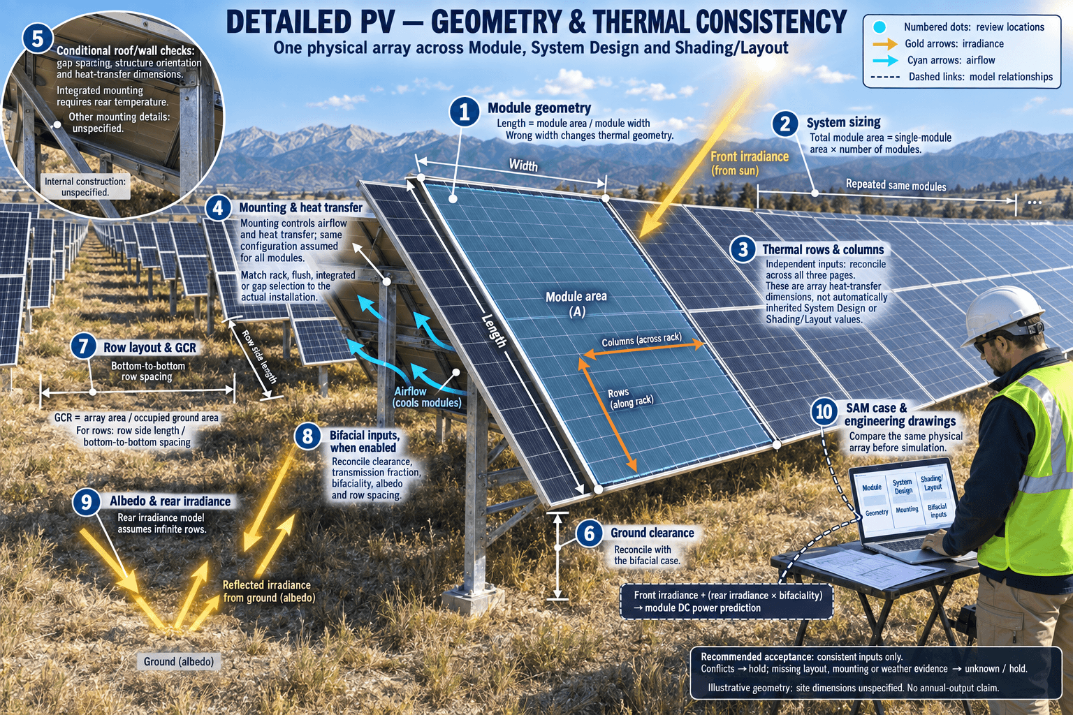
For a detailed PV model, the acceptance check should confirm that the module geometry, array geometry, mounting assumptions, and shading/layout inputs describe the same physical array before simulation results are accepted. SAM explicitly warns that the rows and columns used for module heat-transfer dimensions are independent of similar variables on the System Design page and Shading and Layout page, and says users should verify that values on the different pages are consistent before running a simulation (NREL SAM Module Help, n.d.).
What the Check Should Compare
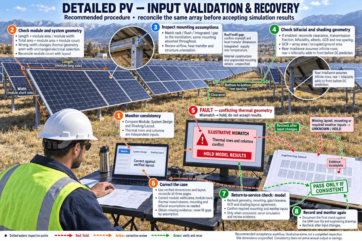
The check should compare the Module page inputs against the System Design and Shading/Layout assumptions that define the same array. On the Module page, relevant geometry inputs include module area, module width, derived module length, and, when array heat-transfer dimensions are selected, rows of modules and columns of modules in the array (NREL SAM Module Help, n.d.). SAM calculates module length from module area divided by module width, so a wrong width can change the modeled thermal geometry even when the electrical module selection is unchanged (NREL SAM Module Help, n.d.).
For the system-level side, the check should confirm that total module area is consistent with the detailed PV relationship: total module area equals the area of one module multiplied by the number of modules in the system (NREL SAM PVWatts System Design Help, n.d.). Where row spacing affects the model, the check should also verify that the ground coverage ratio, row geometry, and shading/layout assumptions describe the same physical row arrangement. SAM describes GCR as the photovoltaic array area divided by the ground area occupied by the array, and for row-based arrays as the side length of one row divided by the distance between the bottom of one row and the bottom of its neighboring row (NREL SAM PVWatts System Design Help, n.d.).
Thermal Consistency to Confirm
The acceptance check should confirm that the selected mounting configuration matches the modeled physical installation. SAM states that mounting configuration affects air movement around the module and heat transfer between the module and the building surface or ground, and assumes all modules in the array use the same mounting configuration (NREL SAM Module Help, n.d.). If the model uses rack, flush, integrated, or gap mounting, the selected option should match the physical layout used on the system design and shading/layout pages.
For roof or wall gap configurations, the check should confirm that the spacing between the module back and roof or wall surface, mounting-structure orientation, and heat-transfer dimensions are aligned with the array layout. For integrated mounting, the check should confirm that the temperature behind the module is supplied, because SAM requires that input for integrated mounting (NREL SAM Module Help, n.d.). If the array-dimensions option is used for heat transfer, the reviewer should treat its rows and columns as thermal inputs that must be reconciled with the actual modeled array, not as automatically inherited values.
Bifacial and Shading-Related Geometry
If bifacial modeling is enabled, the check should confirm that bifacial geometry inputs are compatible with the same row layout used elsewhere. SAM’s bifacial model calculates rear-side plane-of-array irradiance assuming infinite rows, then multiplies rear-side irradiance by the bifaciality factor and adds it to front-side irradiance before module DC power prediction (NREL SAM Module Help, n.d.). The documented drivers for rear-side irradiance include ground albedo, row-to-row spacing as a function of GCR, and ground clearance height (NREL SAM Module Help, n.d.).
The check should therefore confirm that ground clearance height, transmission fraction, bifaciality, GCR, and shading/layout row geometry do not describe conflicting physical conditions. If the supplied documents do not provide the exact site layout, the correct acceptance result is not “pass by assumption”; it is “unknown until layout, module dimensions, row spacing, mounting, and shading inputs are reviewed together.”
Recommended Acceptance Wording
A practical acceptance criterion is: “Pass only if the module area, module width, calculated module length, number of modules, thermal rows and columns, mounting configuration, standoff or gap details, ground clearance, GCR, and shading/layout row assumptions are internally consistent and represent the same physical array. Fail or hold if the Module page thermal geometry conflicts with System Design or Shading/Layout values, or if required mounting and weather inputs are missing.”
This is a recommendation based on the SAM documentation, not a claim about any specific product, deployment, price, certification, or performance result. The supplied sources do not provide a SOLARTODO-specific detailed PV acceptance checklist, so project teams should document the final check against the actual SAM case file and engineering drawings.
FAQ
What should the acceptance check confirm?
It should confirm that module geometry, thermal rows and columns, mounting configuration, GCR, clearance, and shading/layout assumptions all describe the same physical PV array.
Why compare Module page rows and columns with other pages?
SAM states those thermal-dimension variables are independent of similar variables on the System Design and Shading/Layout pages and should be verified for consistency.
Which module geometry fields matter?
Module area, module width, calculated module length, and rows and columns used for array heat-transfer dimensions are relevant fields in the supplied SAM documentation.
How is detailed PV total module area checked?
The supplied SAM text says detailed PV total module area is the product of one module’s area and the number of modules in the system.
What thermal inputs should be reviewed?
Mounting configuration, standoff or gap spacing, mounting-structure orientation, heat-transfer dimensions, and integrated-mounting rear temperature where applicable should be reviewed.
What should be checked for bifacial modules?
Ground clearance, transmission fraction, bifaciality, albedo, GCR, and row-to-row spacing should be consistent because these affect rear-side irradiance modeling.
Can this check prove annual energy output?
No. The supplied documents support consistency checks for SAM inputs, not a specific annual output, savings figure, or guaranteed performance result.
What if drawings or SAM case details are missing?
The correct status is unknown or hold for evidence, because the supplied sources do not justify assuming that detailed PV geometry and thermal inputs are consistent.
References
- NREL SAM Module Help: Used for detailed PV module models, module geometry, thermal inputs, mounting configuration, bifacial inputs, and SAM’s warning to verify rows and columns across pages. — https://samrepo.nlr.gov/help/pv_module.html
- NREL SAM PVWatts System Design Help: Used for system design concepts including total module area relationships, GCR definition, row spacing, losses, shading, albedo, and bifacial context. — https://samrepo.nlr.gov/help/pvwatts_system_design.html
About the Author

Cinn Song
Founder & Chief Solutions Architect
Cinn Song founded SOLARTODO LIMITED and leads its smart-city infrastructure engineering — from solar, storage and integrated smart poles to the company's push into physical-AI city edge nodes: pole-mounted edge computing, vertical LLMs for smart cities, drone-based O&M with autonomous battery swapping, robotic maintenance, and high-speed counter-UAS interception. Since 2010, he has directed turnkey EPC + BOT delivery across 50+ countries, including telecom monopole supply for national grid operators, off-grid solar street-lighting for African municipalities, and integrated smart-pole programs for Gulf smart cities.
Cite This Article
Cinn Song. (2026). Acceptance Check for Detailed PV Geometry and Thermal Inputs. SOLARTODO. Retrieved from https://solartodo.com/knowledge/what-acceptance-check-should-confirm-that-detailed-pv-module-geometry-and-thermal-inputs-are-consistent-across-the
@article{solartodo_what_acceptance_check_should_confirm_that_detailed_pv_module_geometry_and_thermal_inputs_are_consistent_across_the,
  title = {Acceptance Check for Detailed PV Geometry and Thermal Inputs},
  author = {Cinn Song},
  journal = {SOLARTODO Knowledge Base},
  year = {2026},
  url = {https://solartodo.com/knowledge/what-acceptance-check-should-confirm-that-detailed-pv-module-geometry-and-thermal-inputs-are-consistent-across-the},
  note = {Accessed: 2026-09-25}
}
Published: September 25, 2026 | Available at: https://solartodo.com/knowledge/what-acceptance-check-should-confirm-that-detailed-pv-module-geometry-and-thermal-inputs-are-consistent-across-the
Subscribe to Our Newsletter
Get the latest solar energy news and insights delivered to your inbox.
View All Articles