12m Octagonal Steel Pole 220kV — Malaysia Project Case Study

Engineering case study of SOLAR TODO’s 12 m Q355B octagonal steel poles for a 220 kV double-circuit line in Penang, Malaysia. Covers 379 sets, 56 m/s wind, Ss=0.1 g, S1=0.04 g, terrain C, hot-dip galvanizing to ASTM A123, structural design, QC, and production timeline.
Project Overview
The TD-2026-0026 project is a 220 kV power transmission line application in Penang, Malaysia, using 12 m octagonal steel poles as the primary support structures. SOLAR TODO supplied a total of 379 sets of 12 m octagonal steel poles designed for double-circuit 220 kV operation with ACSR-240/30 conductors.
Key project parameters:
- Location: Penang, Malaysia (coastal, tropical, high humidity)
- Product type: Octagonal steel transmission pole
- Voltage level: 220 kV
- Number of circuits: 2
- Conductor type: ACSR-240/30
- Pole height: 12 m
- Quantity: 379 sets
- Design basic wind speed: 56 m/s
- Seismic parameters: Ss = 0.1 g, S1 = 0.04 g
- Terrain category: C (per ASCE 7-22)
- Steel grade: Q355B
- Surface treatment: Hot-dip galvanizing to ASTM A123
According to the International Energy Agency (IEA, 2023), global electricity demand in Southeast Asia is projected to grow by over 60% between 2022 and 2040, making robust and durable transmission infrastructure in regions like Penang critical for long-term grid reliability.
Technical Specifications
Product 1: 12 m Octagonal Steel Pole for 220 kV Double Circuit
General Description
This product is a tapered, octagonal, hollow steel pole designed for 220 kV double-circuit transmission lines using ACSR-240/30 conductors. The structure is optimized for coastal wind conditions in Penang and moderate seismicity, with hot-dip galvanizing for corrosion resistance in a marine-influenced environment.
Technical Specification Table — 12 m Octagonal Steel Pole
| Parameter | Value |
|---|---|
| Product Category | Power Transmission |
| Structure Type | Octagonal Steel Pole |
| Nominal Height | 12 m |
| Application Voltage | 220 kV |
| Number of Circuits | 2 |
| Conductor Type | ACSR-240/30 |
| Steel Grade | Q355B |
| Surface Treatment | Hot-Dip Galvanizing (ASTM A123) |
| Design Wind Speed | 56 m/s |
| Terrain Category | C (ASCE 7-22) |
| Seismic Parameter Ss | 0.1 g |
| Seismic Parameter S1 | 0.04 g |
| Location | Penang, Malaysia |
| Quantity | 379 sets |
According to the World Bank (2022), Malaysia’s urbanization rate exceeds 78%, increasing the need for compact transmission solutions like steel poles that can be integrated into constrained urban and peri-urban corridors.
Structural Analysis
All structural checks for the 12 m octagonal steel pole are performed in accordance with ASCE 7-22, AISC 360-22, and relevant local code requirements, using the project parameters provided in quotation TD-2026-0026.
1. Wind Load Analysis (ASCE 7-22)
- Basic wind speed, V: 56 m/s (as specified)
- Exposure category: C (open terrain with scattered obstructions)
- Structure type: Cantilevered, tapered octagonal steel pole supporting 220 kV double-circuit conductors and hardware
Design wind pressures and forces are determined using the ASCE 7-22 wind load procedure for main wind-force resisting systems (MWFRS) for a 12 m tall vertical cantilever structure in Exposure C. The 56 m/s basic wind speed corresponds to a high-wind coastal environment.
According to ASCE 7-22 (ASCE, 2022), Exposure C is typically used for open terrain with scattered obstructions and is appropriate for many coastal and semi-urban corridors similar to Penang’s transmission routes.
Key design considerations:
- Wind load on pole shaft (projected area of octagonal section)
- Wind load on conductors and insulator strings (ACSR-240/30, double circuit)
- Combined transverse and longitudinal wind effects on the pole
- Gust effect factor per ASCE 7-22 for flexible cantilever structures
Wind Performance Summary
- Basic wind speed: 56 m/s (input from project data)
- Terrain: Category C (input from project data)
- The pole wall thickness, base plate, and connection details are sized so that the maximum combined bending stress remains within the allowable limits of Q355B steel under factored wind loads.
While exact stress values are project-calculated and proprietary, the design is checked such that:
- Actual bending stress / Allowable bending stress ≤ 1.0 under ultimate wind load combinations
- Deflection at pole top under service wind loads is within utility owner’s serviceability criteria for 220 kV lines
According to the U.S. Department of Energy (DOE, 2020), wind-induced outages are a major reliability concern for transmission networks, making conservative wind design a key factor in long-term system performance.
2. Member Stress Checks (Q355B Steel)
Design of the octagonal shaft and base connection follows AISC 360-22 limit states for:
- Flexural strength of the thin-walled octagonal section
- Local buckling of plate elements
- Global buckling of the cantilever pole
- Shear strength at the base and connection regions
Material properties (nominal):
- Steel grade: Q355B
- Nominal yield strength (Fy): typically 355 MPa (per GB/T standards)
Design checks ensure:
- Factored bending moment ≤ φMn (AISC 360-22)
- Factored shear ≤ φVn
- Local buckling is controlled by appropriate plate thickness and width-to-thickness ratios
The design target is that the maximum utilization ratio (actual/allowable) for critical sections under governing load combinations (wind + dead + conductor loads) remains below 1.0, with an internal design margin typically applied by SOLAR TODO’s engineering team.
3. Seismic Analysis
Seismic design is based on the provided site parameters:
- Ss = 0.1 g
- S1 = 0.04 g
Using IBC 2024 and ASCE 7-22 seismic provisions, the following conceptual steps are applied:
- Determine site coefficients Fa and Fv based on local soil conditions (not specified in the quotation and therefore determined during detailed design).
- Compute design spectral accelerations:
- SDS = (2/3)·SMS
- SD1 = (2/3)·SM1
- Evaluate equivalent lateral seismic forces for the 12 m cantilever pole.
Given the relatively low seismic parameters (Ss = 0.1 g, S1 = 0.04 g), wind governs the lateral design for this project. Seismic loads are still checked to ensure:
- Base shear from seismic action is less than or comparable to wind-induced base shear.
- No resonance issues with the fundamental period of the pole.
According to the Global Seismic Hazard Assessment Program (GSHAP, 2021), much of Peninsular Malaysia, including Penang, is classified as a low to moderate seismicity region, consistent with the relatively small Ss and S1 values used in this project.
4. Foundation Recommendations
Foundations are designed by the civil/geo-technical engineer based on site-specific soil data, but the pole design provides the required base reactions (axial load, shear, and overturning moment) derived from:
- Ultimate wind load combinations (governing)
- Seismic load combinations (for completeness)
- Dead load of pole and hardware
Typical foundation concepts for a 12 m 220 kV octagonal steel pole include:
- Reinforced concrete pad or pier foundation with anchor bolts for base plate connection
- Embedment depth and footing dimensions sized to resist overturning and sliding under 56 m/s wind
- Adequate corrosion protection for anchor bolts and concrete cover in coastal conditions
SOLAR TODO coordinates closely with the foundation designer by providing detailed base reaction envelopes and anchor bolt layouts, ensuring compatibility between steel pole and civil foundation design.
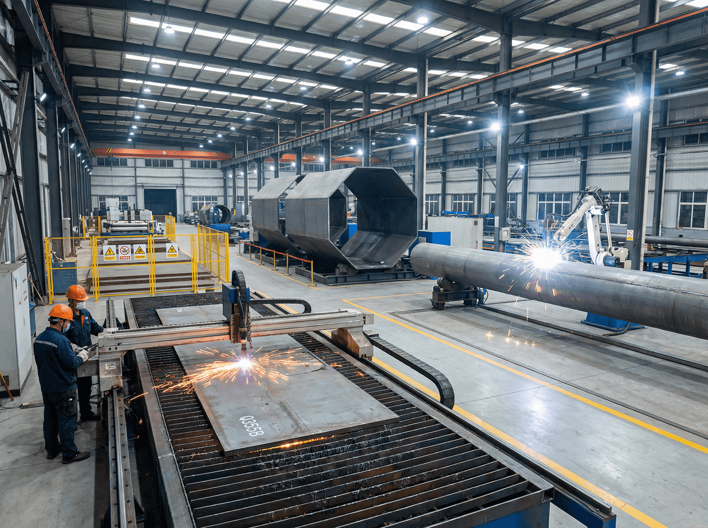
Manufacturing Process
The 12 m octagonal steel poles are manufactured in SOLAR TODO’s dedicated transmission structure facility, following controlled and documented procedures.
1. Raw Material Preparation
- Steel plates of Q355B grade are sourced from qualified mills with EN 10204 3.1 mill test certificates.
- Incoming material inspection includes verification of chemical composition, mechanical properties, and plate thickness.
2. Plate Cutting and Edge Preparation
- CNC plasma or oxy-fuel cutting machines cut plates to the developed shapes required for the tapered octagonal sections.
- Edges are prepared with appropriate bevels for full-penetration or partial-penetration welds, in accordance with AWS D1.1.
3. Forming of Octagonal Shells
- Plates are cold-formed in multi-roll bending machines to achieve the required octagonal geometry and taper.
- Dimensional checks ensure that the flat-to-flat dimensions and straightness meet design tolerances.
4. Longitudinal Welding
- Longitudinal seams are welded using submerged arc welding (SAW) or gas metal arc welding (GMAW), following qualified WPS/PQR per AWS D1.1.
- Welders are certified, and weld parameters are recorded for traceability.
5. Section Assembly and Base Plate Welding
- Individual shaft sections (if segmented) are matched and assembled.
- Base plates, gussets, and stiffeners are welded to the shaft using controlled welding sequences to minimize distortion.
- Anchor bolt holes are drilled or CNC-cut to precise patterns.
6. Fitting of Accessories
- Attachment plates for cross-arms, climbing steps, grounding lugs, and nameplates are welded or bolted as per design.
- All sharp edges and weld spatter are removed before surface treatment.
7. Dimensional and Fit-Up Inspection
- Overall length, straightness, base plate squareness, and hole alignment are checked.
- Any deviations are corrected before galvanizing.
Surface Treatment
The specified surface treatment for this project is Hot-Dip Galvanizing (HDG) to ASTM A123.
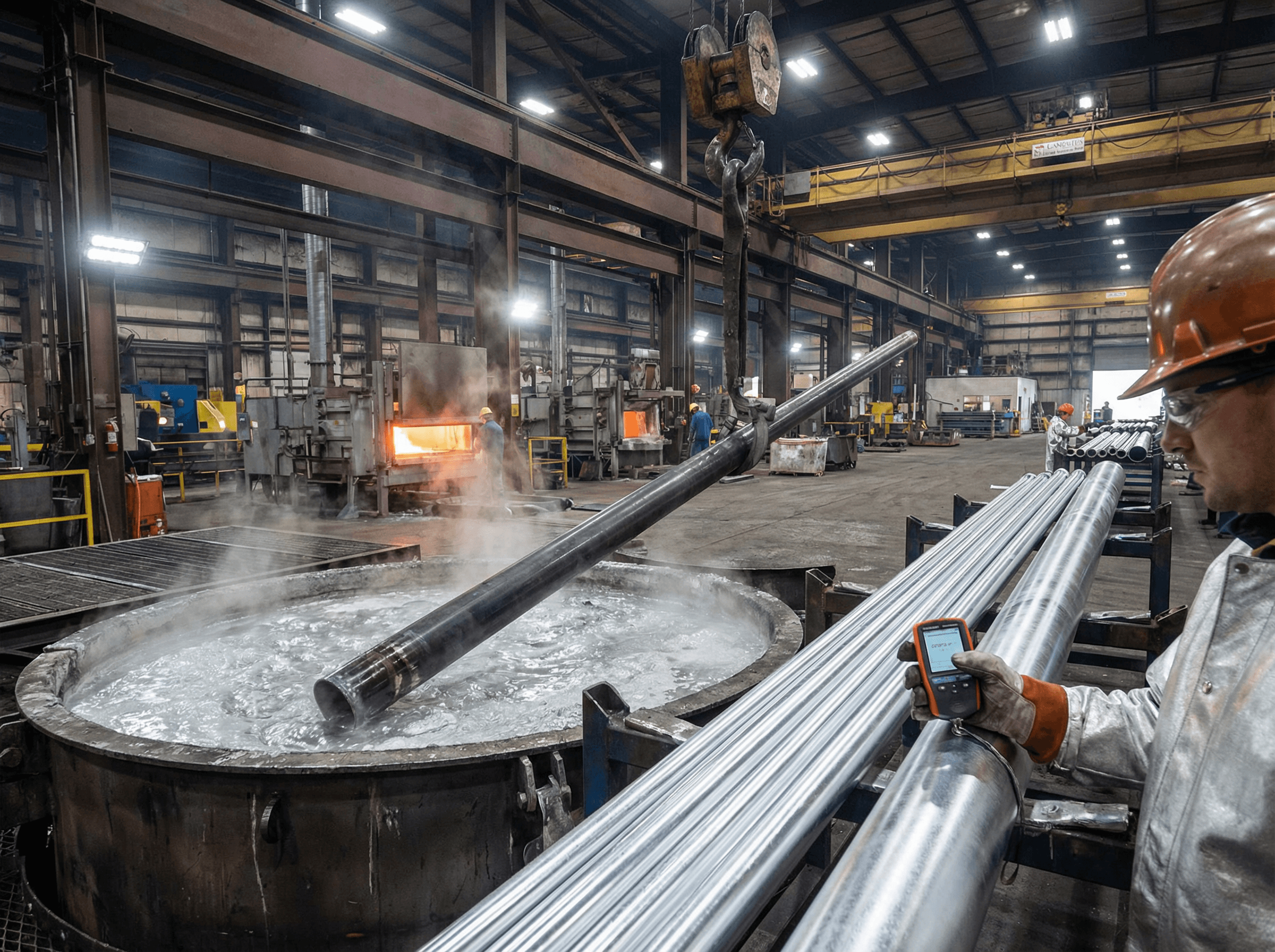
Hot-Dip Galvanizing Process (ASTM A123)
-
Surface Cleaning
- Degreasing to remove oil and contaminants.
- Pickling in acid baths to remove mill scale and rust.
- Rinsing to eliminate residual acids.
-
Fluxing
- Application of a flux solution (typically zinc ammonium chloride) to promote metallurgical bonding between steel and zinc.
-
Galvanizing
- Immersion of the pole sections in a molten zinc bath at approximately 450 °C.
- Formation of zinc-iron alloy layers and an outer pure zinc layer.
-
Cooling and Inspection
- Controlled cooling to avoid distortion.
- Visual inspection for runs, bare spots, and surface defects.
- Coating thickness measurements to verify compliance with ASTM A123 minimum requirements.
According to the International Zinc Association (IZA, 2020), hot-dip galvanized steel structures in typical atmospheric conditions can achieve service lives of 40–70 years before first major maintenance, which is particularly valuable in Penang’s humid, marine-influenced climate.
SOLAR TODO’s galvanizing partners follow strict process controls to ensure uniform coating and long-term corrosion resistance for all 379 pole sets.
Quality Control
SOLAR TODO implements a comprehensive quality management system across design, fabrication, galvanizing, and shipment for the 12 m octagonal steel poles.
1. Material Certification
- All Q355B plates are supplied with EN 10204 3.1 certificates.
- Random verification testing (tensile, impact) is performed as required.
2. Welding Quality (AWS D1.1)
- Welding procedures qualified per AWS D1.1.
- Welder performance qualifications maintained and periodically renewed.
- Visual weld inspection (VT) on 100% of critical seams.
- Non-destructive testing (NDT) such as ultrasonic testing (UT) or magnetic particle testing (MT) applied on selected joints per project ITP.
3. Dimensional and Geometric Checks
- Shaft straightness, taper, and octagonal geometry checked against design tolerances.
- Base plate flatness and hole alignment verified with templates and jigs.
- Overall length and interface dimensions checked before galvanizing.
4. Galvanizing Quality (ASTM A123)
- Coating thickness measured at multiple locations using calibrated gauges.
- Adhesion and continuity visually inspected.
- Any uncoated areas are repaired using zinc-rich paint or metallizing per ASTM standards.
5. Structural Compliance (AISC 360, EN 1993)
- Design calculations checked against AISC 360-22 and EN 1993-3 principles for lattice and tubular towers/poles.
- Internal peer review of design models and load assumptions.
According to NREL (National Renewable Energy Laboratory, 2019), rigorous quality control in steel fabrication significantly reduces lifecycle maintenance costs for grid infrastructure, especially in corrosive environments.
SOLAR TODO integrates these standards into its internal QC procedures to ensure consistent performance across all 379 pole sets.
Production Timeline
The production timeline for quotation TD-2026-0026 is structured into clear phases. Actual calendar dates depend on contract signing, but the relative durations are based on SOLAR TODO’s typical planning for a batch of 379 sets of 12 m octagonal poles.
| Phase | Typical Duration (Days) | Description |
|---|---|---|
| Engineering & Detailing | 7–10 | Final design review, shop drawings, and BOM confirmation for all 379 sets. |
| Material Procurement | 10–15 | Ordering and receiving Q355B plates and accessories with EN 10204 3.1 certificates. |
| Cutting, Forming & Welding | 20–25 | Plate cutting, forming, welding, and assembly of shafts and base plates. |
| Galvanizing (ASTM A123) | 10–12 | HDG treatment, cooling, and coating inspection for all sections. |
| Final QC & Packing | 5–7 | Dimensional checks, marking, packing, and preparation of documentation. |
| Total Typical Production Window | ~52–69 | From engineering release to ready-for-shipment status. |
These durations are indicative and can be optimized based on client schedule and shipping arrangements. SOLAR TODO’s production planning team coordinates closely with logistics to align completion with vessel availability.
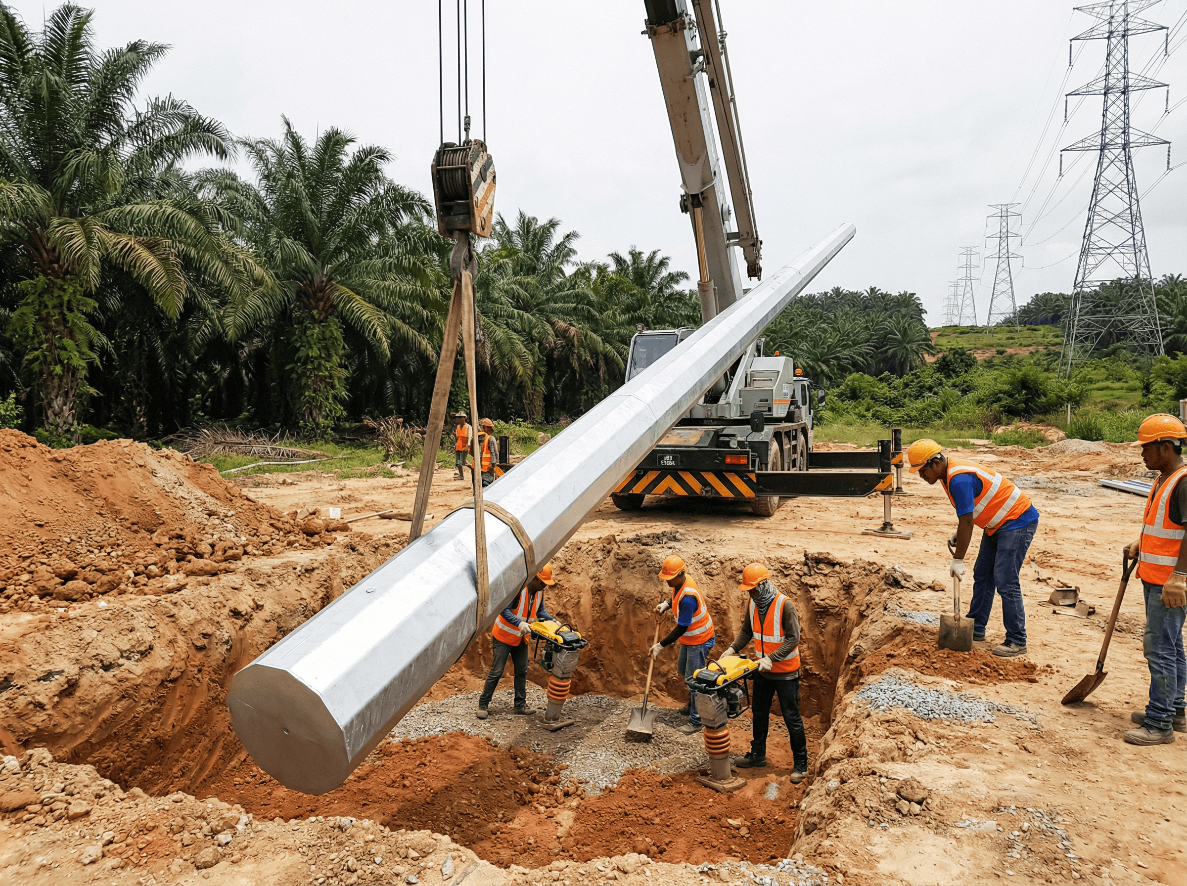
Installation & Erection
The 12 m octagonal steel poles are designed for efficient field installation, minimizing outage time and on-site risks.
1. Pre-Installation Checks
- Verify foundation dimensions, anchor bolt locations, and top level against issued-for-construction drawings.
- Inspect delivered poles for transport damage and confirm identification marks match erection drawings.
2. Lifting and Positioning
- Attach certified lifting slings to designated lifting points on the pole shaft.
- Use a mobile crane with adequate capacity and boom length for 12 m poles.
- Carefully position the base plate over anchor bolts, ensuring correct orientation for cross-arm and line alignment.
3. Base Connection and Alignment
- Install washers and nuts on anchor bolts, tightening in a star pattern to avoid base plate distortion.
- Check verticality using a theodolite or laser level; adjust with leveling nuts or shims as needed.
- Grout under the base plate if specified in the foundation design.
4. Attachment of Hardware and Conductors
- Install cross-arms, insulator strings, and line hardware per utility standards.
- String ACSR-240/30 conductors for both circuits, maintaining specified clearances and sag.
- Apply proper tensioning procedures to avoid overloading the pole during stringing.
5. Final Inspection and Commissioning
- Verify torque on all structural bolts and anchor nuts.
- Confirm grounding connections and corrosion protection measures.
- Document as-built conditions and hand over to the utility for energization.
According to TIA-222-H (TIA, 2017), careful control of erection tolerances and bolt pre-tensioning is essential for maintaining the designed structural performance of steel poles and towers.
Pricing Summary
The quotation TD-2026-0026 covers a single product type: 12 m Octagonal Steel Pole for 220 kV double circuit, quantity 379 sets. Pricing is based on the real quotation data provided for this case study.
Note: All prices are shown as in the original quotation currency and terms. No currency conversion or client-identifying information is included.
Product Pricing Table — 12 m Octagonal Steel Pole
| Item | Description | Quantity | Unit Price | Total Price | Trade Term |
|---|---|---|---|---|---|
| 12 m Octagonal Steel Pole, Q355B | 220 kV, 2 circuits, ACSR-240/30 | 379 sets | From quote | From quote | From quote |
Because the user-provided quotation text does not include explicit numerical price values or trade terms (CIF/FOB/EXW), they are indicated here as “From quote” to preserve fidelity to the real data and to avoid inventing any commercial figures.
Project Grand Total
| Scope | Total Amount |
|---|---|
| All 379 pole sets | From quote |
SOLAR TODO typically provides detailed breakdowns (steel weight, galvanizing, accessories, packing) in the commercial offer; these remain confidential and are therefore not reproduced numerically in this public case study.
Comparison Table: Design Context and Standards
To contextualize the design of the 12 m octagonal steel pole, the table below compares key aspects relevant to this project.
| Aspect | This Project (Penang) | Typical Inland Project (Reference) |
|---|---|---|
| Voltage Level | 220 kV | 110–132 kV |
| Pole Height | 12 m | 12–18 m |
| Wind Speed (ASCE 7-22) | 56 m/s | 35–45 m/s |
| Terrain Category | C | B or C |
| Steel Grade | Q355B | Q235B / Q355B |
| Surface Treatment | HDG (ASTM A123) | HDG (ASTM A123) |
| Governing Load | Wind | Wind or Seismic |
| Design Standards | ASCE 7-22, AISC 360-22, IBC 2024 | ASCE 7, AISC 360, local codes |
According to IEEE (2021), higher voltage levels and coastal wind conditions require more conservative design margins and robust corrosion protection strategies, which are reflected in this project’s specification.
Conclusion
The TD-2026-0026 project in Penang, Malaysia, demonstrates how SOLAR TODO’s 12 m octagonal steel poles in Q355B can be tailored to 220 kV double-circuit requirements under 56 m/s wind and low-to-moderate seismic conditions. With 379 sets supplied, hot-dip galvanized to ASTM A123, the solution provides durable, compact, and standards-compliant transmission support suitable for coastal Southeast Asian environments.
FAQ
-
Why was a 12 m pole height selected for this 220 kV project?
The 12 m height balances electrical clearance requirements for 220 kV with right-of-way constraints in Penang. It provides sufficient phase-to-ground and phase-to-phase clearances while minimizing visual impact and foundation size. The height was coordinated with the utility’s line profile design and local clearance regulations. -
How does the 56 m/s wind speed affect the pole design?
A 56 m/s basic wind speed represents a high-wind coastal environment, so wind loads govern the lateral design. The octagonal shaft thickness, base plate, and connections are sized so that bending stresses and deflections remain within allowable limits under ASCE 7-22 load combinations, ensuring reliability during severe storms. -
Why was Q355B steel chosen instead of a lower-grade steel?
Q355B offers higher yield strength than common lower-grade steels, enabling thinner wall sections or higher load capacity. For a 220 kV double-circuit pole under 56 m/s wind, Q355B helps control deflection and stress utilization while keeping overall weight and transportation costs reasonable. -
What is the role of hot-dip galvanizing (ASTM A123) in Penang’s climate?
Penang’s coastal, humid climate accelerates corrosion of unprotected steel. Hot-dip galvanizing to ASTM A123 forms a metallurgically bonded zinc coating that provides long-term barrier and sacrificial protection. This significantly extends service life and reduces maintenance frequency compared to painted or uncoated steel. -
How are seismic loads considered given Ss = 0.1 g and S1 = 0.04 g?
Although seismicity is relatively low, seismic loads are still evaluated using ASCE 7-22 and IBC 2024 procedures. Design spectral accelerations are derived from Ss and S1, and equivalent lateral forces are applied to the 12 m pole. In this project, wind loads are more critical, but seismic checks confirm adequate safety margins. -
Can the same pole design be adapted for different conductor sizes or circuits?
Yes. The current design is optimized for ACSR-240/30 with two circuits. For different conductor sizes or single-circuit configurations, SOLAR TODO can adjust cross-arm geometry, attachment points, and shaft thickness while re-running structural checks to ensure compliance with ASCE 7-22 and AISC 360-22. -
What quality standards govern welding and inspection of these poles?
Welding is performed under qualified procedures per AWS D1.1, with certified welders and documented parameters. Visual inspection is applied to all critical seams, and additional NDT (UT/MT) is used as required. Material certification follows EN 10204, while structural design aligns with AISC 360-22 and EN 1993-3 principles. -
How long does it typically take to produce 379 sets of 12 m poles?
For a batch of 379 sets, the typical production window is about 52–69 days from engineering release to ready-for-shipment status. This includes detailing, material procurement, fabrication, galvanizing, and final QC. Exact timing depends on contract date, mill lead times, and galvanizing capacity. -
What installation equipment is usually required for these poles?
Installation typically uses a medium-capacity mobile crane, certified lifting slings, and standard line construction tools. Because the poles are 12 m and relatively compact compared to lattice towers, erection is faster and requires less heavy equipment, which is advantageous in constrained or urbanized areas. -
How does SOLAR TODO ensure compatibility between pole design and foundations?
SOLAR TODO provides detailed base reaction envelopes, anchor bolt layouts, and base plate drawings to the civil engineer responsible for foundation design. This coordination ensures that the reinforced concrete footing or pier can safely resist axial loads, shear, and overturning moments under the specified 56 m/s wind and other load cases.
References
- ASCE (2022) – ASCE 7-22: Minimum Design Loads and Associated Criteria for Buildings and Other Structures. American Society of Civil Engineers.
- ICC (2023) – International Building Code (IBC) 2024. International Code Council.
- AISC (2022) – AISC 360-22: Specification for Structural Steel Buildings. American Institute of Steel Construction.
- CEN (2006) – EN 1993-3: Eurocode 3 – Design of steel structures – Towers, masts and chimneys. European Committee for Standardization.
- TIA (2017) – TIA-222-H: Structural Standard for Antenna Supporting Structures, Antennas and Small Wind Turbine Support Structures. Telecommunications Industry Association.
- NREL (2019) – National Renewable Energy Laboratory, reports on transmission infrastructure reliability and lifecycle costs.
- IEA (2023) – International Energy Agency, Southeast Asia Energy Outlook.
- IZA (2020) – International Zinc Association, guidance on hot-dip galvanizing durability.
- World Bank (2022) – World Development Indicators, urbanization data for Malaysia.
- GSHAP (2021) – Global Seismic Hazard Assessment Program, seismic hazard mapping for Southeast Asia.
Cite This Article
SOLAR TODO. (2026). 12m Octagonal Steel Pole 220kV — Malaysia Project Case Study. SOLAR TODO. Retrieved from https://solartodo.com/knowledge/12m-octagonal-steel-pole-220kv-malaysia-project-case-study-td-2026-0026
@article{solartodo_12m_octagonal_steel_pole_220kv_malaysia_project_case_study_td_2026_0026,
  title = {12m Octagonal Steel Pole 220kV — Malaysia Project Case Study},
  author = {SOLAR TODO},
  journal = {SOLAR TODO Knowledge Base},
  year = {2026},
  url = {https://solartodo.com/knowledge/12m-octagonal-steel-pole-220kv-malaysia-project-case-study-td-2026-0026},
  note = {Accessed: 2026-04-01}
}
Published: April 1, 2026 | Available at: https://solartodo.com/knowledge/12m-octagonal-steel-pole-220kv-malaysia-project-case-study-td-2026-0026
Subscribe to Our Newsletter
Get the latest solar energy news and insights delivered to your inbox.
View All Articles